Injection molding is a high-speed, high-precision process—and ejector pins are one of the unsung workhorses that make part release reliable and repeatable. At Toolingsun we design and build tooling for OEMs and contract manufacturers; understanding ejector pin selection, placement, and maintenance is essential for good DFM, long mold life, and high first-pass yield. This guide explains what ejector pins are, how they work, common materials and types, root causes of ejector-pin marks, and practical selection rules you can apply in your next tooling project.
What Are Ejector Pins in Injection Molding?
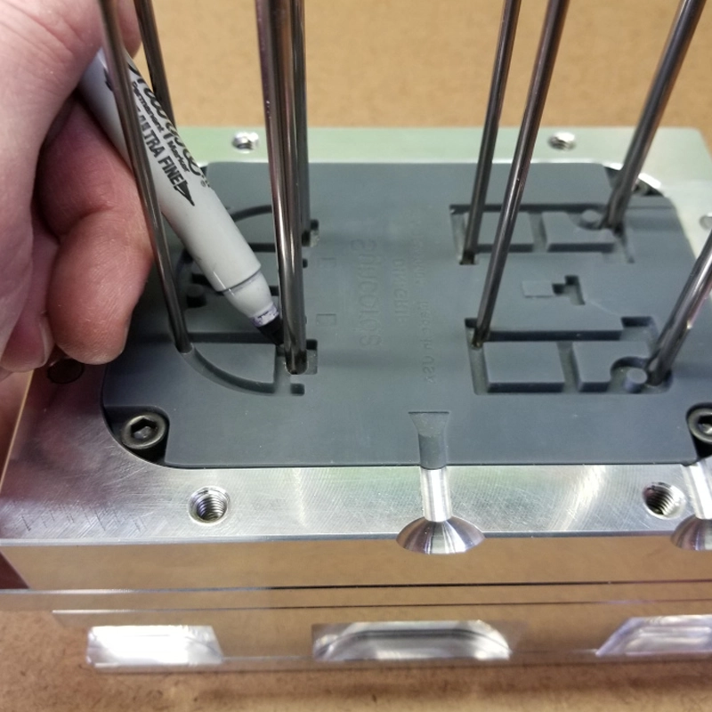
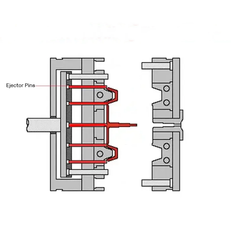
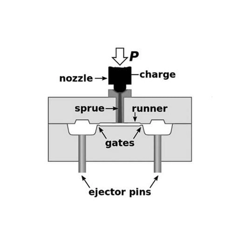
Ejector pins are slender metal rods installed in the ejector plate or ejector retainer of a mold. After the molten plastic cools and the mold halves separate, ejector pins push the part off the core side (and sometimes out of the cavity) so the cycle can continue. Though small, their timing, material, surface finish, and placement directly influence part quality, cycle time, and maintenance intervals.
Common Materials Used for Ejector Pins in Molds
- H13 tool steel (through-hardened) — A widely used choice for durability, toughness, and temperature resistance in high-volume molds.
- Nitrided H13 or surface-nitrided pins — Provide a hard, wear-resistant surface to reduce galling and extend life.
- Stainless steel (e.g., 440C) — Used when corrosion resistance is required, such as in medical or food-grade molds.
- Black (cold-worked) steels — Lower-cost option for low-volume tooling or prototype molds where extreme durability is not essential.
Material selection balances cycle rate, part ejection force, environmental exposure, and cost.
Types of Ejector Pins Used in Injection Molding
- Through-Hard Ejector Pins — Full-through hardened pins with ground, polished tips; ideal for high-volume production where wear resistance and straightness are critical.
- Nitrided H13 Ejector Pins — Pins with a hardened nitrided surface offering excellent wear and galling resistance; commonly used in automotive and glass-filled applications.
- Black Ejector Pins — Economical pins for prototypes or low-pressure applications; lower wear life but acceptable for short runs.
- Other Ejection Components — Includes stripper plates, sleeves, ejector blades, pin-type lifters, and ejector bushes/sleeves used for guided, distributed ejection and where larger contact areas are needed.
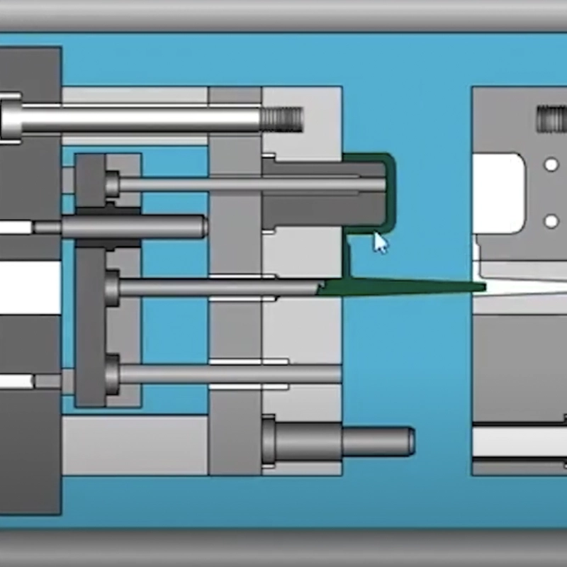
How Do Ejector Pins Work?
1. Injection Phase — With the mold closed, pins are retracted into recesses so the plastic can fill the cavity and form against the core.
2. Cooling Phase — The part solidifies while pins remain retracted, usually while coolant channels maintain temperature control.
3. Ejection Phase — When the mold opens, the ejector system advances: the ejector plate pushes pins forward, applying even, timed force to the part at specified contact points. Parts are guided off cores and onto conveyors or fall plates.
Proper synchronization of plate motion and careful control of stroke length prevents part deformation and flash.
Causes and Solutions of Ejector Pin Marks
Ejector-pin marks (dimples, witness marks, or impressions) are common defects. Typical causes and solutions include:
- Inadequate Cooling Time
- Cause: Part still too soft when ejection begins.
- Solution: Increase cooling time or add conformal cooling. Consider using higher thermal-conductivity inserts.
- Thin-Walled Products
- Cause: Thin sections deform easily under ejection force.
- Solution: Redistribute ejection force with wider stripper plates or use ejector blades/strips to spread load.
- Improper Dwell Time or Temperature
- Cause: Melt or mold temperature incorrect; material not fully solidified.
- Solution: Optimize barrel/mold temperature profile and use process capability studies (Cp/Cpk) to set stable parameters.
- Poor Pin Placement
- Cause: Pins located where the part is sensitive or unsupported.
- Solution: Move pins to ribs, bosses, or thick sections; use non-eject locations for aesthetic faces. Use DFMEA to identify sensitive areas during early DFM.
- Inappropriate Machine or Pressure Settings
- Cause: Excessive clamp or injection pressure; large back-pressure spikes.
- Solution: Tune machine settings, use valve gates or multi-stage packing to reduce internal stresses, and employ consistent shot profiles.
- Additional Preventive Measures
- Polish pin tips, use domed or flanged pin heads to reduce impression area, add rubber buffers on the stripper plate for soft landing, and specify pin tip surface finish (Ra) and hardness to reduce marking and galling. For visible surfaces, avoid pin ejection or use ejector sleeves that hide the mark beneath a boss.
How to Choose the Right Ejector Pins
Selecting pins requires engineering judgment:
- Pin Diameter — Larger diameters reduce stress concentration and tendency to bend; choose based on ejection force and part geometry.
- Pin Length and Size — Minimize unsupported length to prevent deflection; use guided sleeves for long stroke pins.
- Material Strength — For high-temperature, glass-filled, or abrasive grades, choose hardened or nitrided pins to resist wear.
- Material Type — Match corrosion or hardness needs to the application; stainless for corrosion, H13 for thermal cycling.
- Cost Considerations — Balance upfront cost vs maintenance interval; hardened/nitrided pins cost more but reduce downtime and scrap.
Include pins in the mold bill of materials and define maintenance intervals based on cycle count and part material.
Conclusion
Ejector pins are small components with a big impact. Thoughtful selection of material, diameter, placement, and pin type—combined with robust DFM, proper cooling, and tuned process parameters—eliminates many common defects and extends mold life. As a tooling manufacturer and factory, Toolingsun partners with moldmakers and suppliers to implement best practices: optimized ejector layouts, hardened pin specifications, and maintenance plans that maximize uptime.
If you’re seeing ejector-pin marks, unexpected pin wear, or inconsistent ejection on your parts, send us your part drawing and cycle report. Our mold engineers will review pin placement, suggest DFM changes, and recommend a maintenance and retrofit strategy to improve yield and reduce downtime. Let Toolingsun help you design injection tooling that performs reliably in production.