Are you planning a die casting project and worried the tool might make or break your part? At Toolingsun, we hear that concern every day. As a factory and manufacturer with deep die casting experience, we design molds not just to shape metal but to control flow, thermal behavior, and part accuracy from first shot to the millionth. In this guide we’ll walk you through why mold design matters, what a die casting mold contains, the different mold types you might choose, the step-by-step design workflow, and the technical details that separate a short-lived tool from a production workhorse. If you need OEM service, DFM support, or a supplier who understands both engineering and shop-floor realities, read on — and feel free to contact our team for a tailored consultation.
Why the mold is the heart of die casting
In die casting, the mold plays a far larger role than simply defining geometry. When molten aluminum, zinc, or magnesium is injected at high pressure, the cavity shape, runner layout, vents, cooling strategy, and ejection scheme determine porosity levels, surface quality, dimensional stability, and cycle time. A poorly conceived mold leads to common defects such as porosity, cold shuts, flash, warpage, and premature tool wear. Conversely, a well-engineered mold improves yield, reduces scrap, extends tool life, and makes downstream secondary operations far easier. As a manufacturer and supplier, our goal at Toolingsun is to design tooling that delivers repeatable parts and predictable production economics.
Core components of a die casting mold
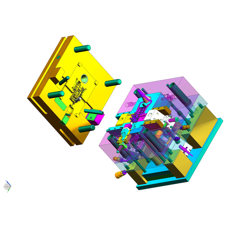
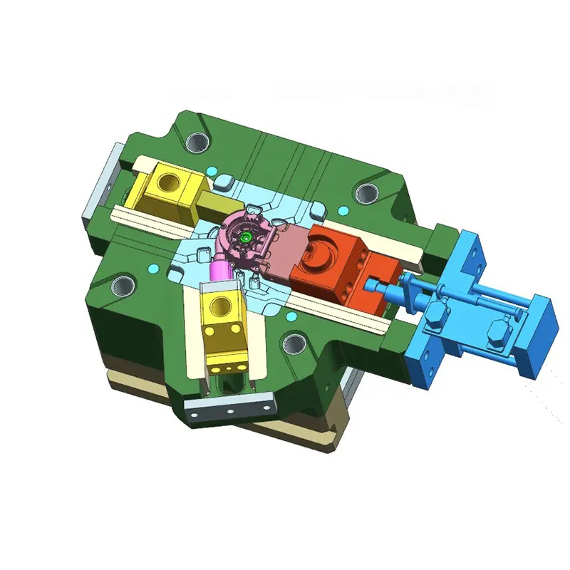
A typical die casting tool is a complex assembly of engineered elements. Understanding each piece helps you appreciate the design tradeoffs.
- Cavity and core: The cavity shapes the external surfaces, while the core forms internal features and hollows. Accurate machining and proper surface finish here are essential for dimensional control and part ejection.
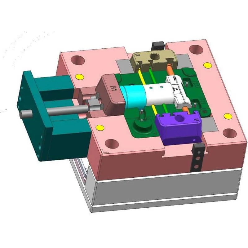
- Inserts and sliders: These provide undercuts, threads, and core pulls without requiring a fully segmented die. Sliders and cam-driven inserts allow complex geometry while preserving parting line simplicity.
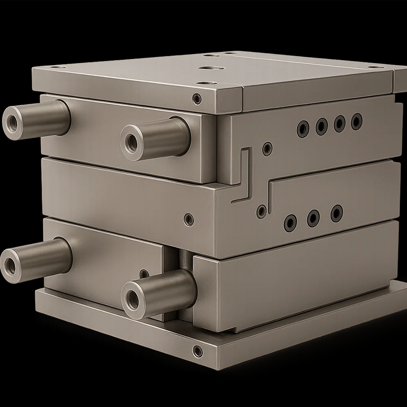
- Mold base system: Hardened plates, guide pillars, and frames form the structural backbone that mounts to the die casting machine. A rigid base preserves alignment under high injection forces.
- Runner, gate, and sprue system: These channels direct molten metal into cavities. Proper gate size and runner geometry reduce turbulence, prevent premature solidification, and limit air entrapment.
- Overflow and venting: Overflows and vents evacuate trapped gases and help avoid porosity. Their placement and sizing are critical to part integrity.
- Ejection system: Ejector pins, sleeves, and stripper plates withdraw the solidified casting without damage. Thoughtful pin placement and draft design prevent stuck parts and surface blemishes.
- Cooling channels and thermal control: Conformal or straight drilled cooling paths manage solidification rates. Uniform cooling prevents warpage and minimizes cycle time.
- Support and fasteners: Dowels, locating pins, and bolts maintain repeatability and provide serviceability for maintenance.
Types of dies and when to use them
Selecting the right mold type depends on volume, part complexity, and budget.
- Prototype dies: Low-cost, quick-turn molds for trial runs and design validation. They use softer steels or partially hardened plates. Use them to verify geometry, gate location, and partability before investing in a production die.
- Rapid tooling: Additive or hybrid approaches produce tools quickly for small runs or urgent requirements. They bridge prototype validation and early production without long lead times.
- Production dies: Hardened tool steel construction designed for longevity and repeatable tolerances. These are suitable for high-volume runs and feature optimized cooling, eject systems, and wear-resistant coatings.
- Modular or unit dies: Modular inserts and standard bases reduce cost for families of parts. These work well when volumes are moderate and product variants are common.
- Trim dies: Separate trimming tooling removes gates, flash, and overflows. Integrating trimming with the die casting cell reduces manual labor and improves part consistency.
The mold design process: a manufacturer’s workflow
Toolingsun follows a disciplined design-for-manufacture (DFM) and supplier collaboration process that minimizes surprises.
- Concept and DFM review
We start with part geometry, nominal tolerances, and functional requirements. Early DFM guidance addresses wall-thickness uniformity, draft angles, rib placement, and boss design to reduce defects and machining work. - Material and process selection
Alloy choice and die casting method (hot-chamber vs cold-chamber) determine gate sizing, thermal loads, and die materials. We select tool steels, coatings, and hardening processes to match expected cycle count and abrasive wear. - Cavity layout and gating strategy
We iteratively place gates, runners, and overflows to ensure smooth fill patterns. The goal is uniform fill front progression and minimal turbulence to reduce entrapped air and shrink porosity. - Cooling and thermal modeling
Cooling channel design balances solidification profile and cycle time. Where needed, conformal cooling or baffles are used to eliminate hot spots and reduce warpage. - Mold kinematics and ejection design
We design slides, lifters, and ejector pin patterns to release the part cleanly without distortion. Draft angles and surface textures are finalized with ejection in mind. - CAE simulation and preproduction validation
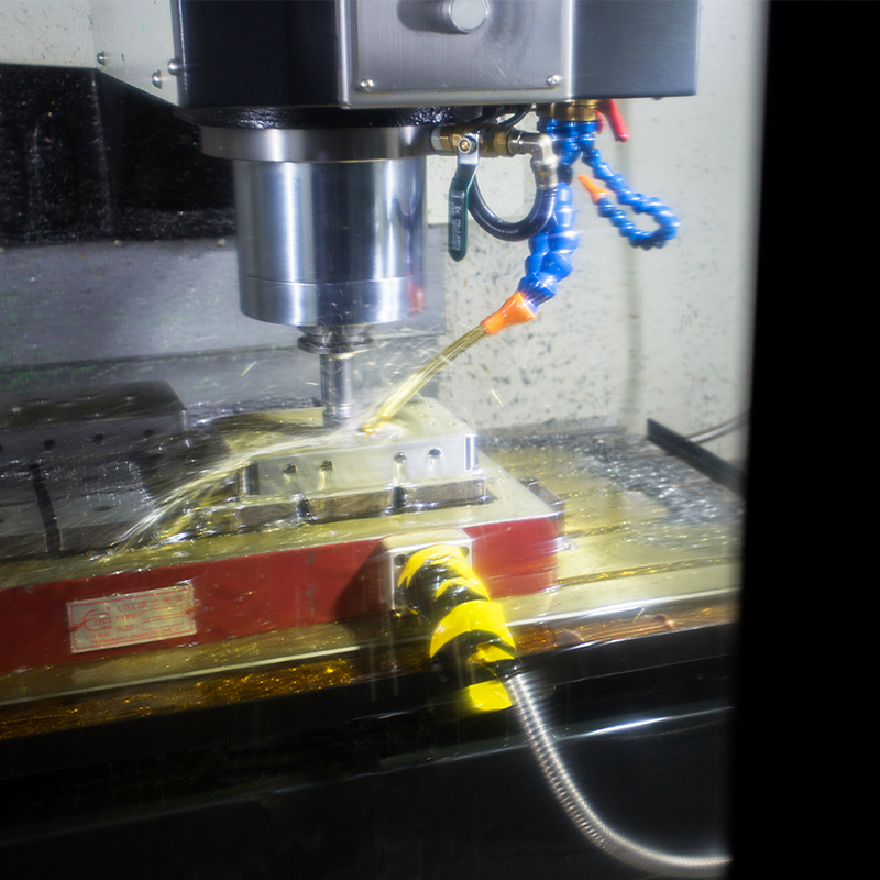
Flow, solidification, and thermal simulations validate gate placement, venting, and expected porosity zones. Simulation allows us to refine the tool before machining begins. - Toolmaking and tryout
After machining and heat treatment, we assemble the die and run trial shots. Tool tryout confirms partability and identifies final tuning for gate size, shot weight, and thermal cycles. - Production validation and lifecycle planning
Once validated, we document process windows, maintenance intervals, and spare part lists to keep the die running reliably in production.
Key design factors that determine success
Successful die tooling balances many variables. Pay special attention to:
- Draft: Proper draft angles ease ejection and limit surface scratches. Internal cores often need greater draft due to shrink behavior.
- Wall thickness: Maintain uniform wall thickness to prevent hot spots and sinking. Use ribs and bosses to add stiffness without thickening walls.
- Fillets and radii: Generous fillets reduce stress concentration and improve metal flow. Sharp corners increase the risk of cold shuts and tool fatigue.
- Parting line location: Well-chosen parting lines minimize flash and simplify slide use. Poor parting can increase secondary trimming and scrap.
- Gate and runner sizing: Correct gate design prevents premature freezing and excessive turbulence. Gates also influence cosmetic surface quality.
- Venting and overflow placement: Timely venting eliminates trapped gases that produce porosity. Overflows capture cold metal fronts and protect the cavity.
- Material and heat-treatment of the die: Tool steel selection and hardening determine wear resistance and service life. Coatings extend life in abrasive processes.
- Serviceability: Design for maintenance by making wear components replaceable and providing easy access to cooling circuits and slides.
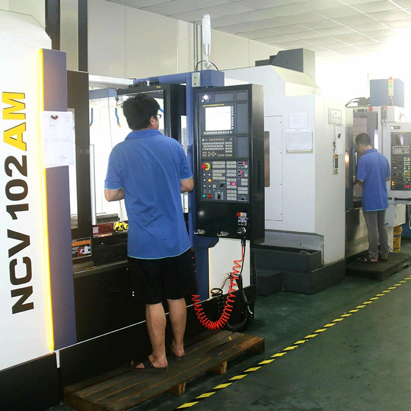
Industry best practices and modern tools
Leading manufacturers combine simulation, precision toolmaking, and data-driven process control. CAE reduces trial-and-error. Advanced cooling, PVD coatings, and real-time thermal monitoring extend die life and improve cycle consistency. Working with a supplier who offers OEM service and full DFM collaboration shortens the path from prototype to stable production.
Conclusion and next steps
If your program depends on consistent part quality, low scrap, and predictable tool life, the mold should be the first engineering decision you optimize. At Toolingsun, we pair seasoned die designers with in-house toolmaking and production expertise to deliver DFM-backed molds, OEM service, and full lifecycle support. Whether you need a prototype die, rapid tooling for a pilot run, or hardened production tooling for high-volume manufacturing, our factory can support your project from CAD to validated production. Contact Toolingsun for a DFM review, supplier quote, or to start a project plan that aligns part design, tooling strategy, and production goals. Let’s build a mold that makes your part perform consistently and profitably.