Thanks — if you’re wrestling with undercuts in a new part design, you’re in the right place. At Toolingsun we see undercuts every day and solve them routinely for customers across consumer, medical, and industrial markets. Below I’ll walk you through six proven engineering strategies for producing molded parts with undercuts reliably and cost-efficiently, explain when each approach makes sense, and share practical tips from our factory floor so you can make decisions that save time and money in tooling and production.
Understanding the problem: what makes undercuts difficult
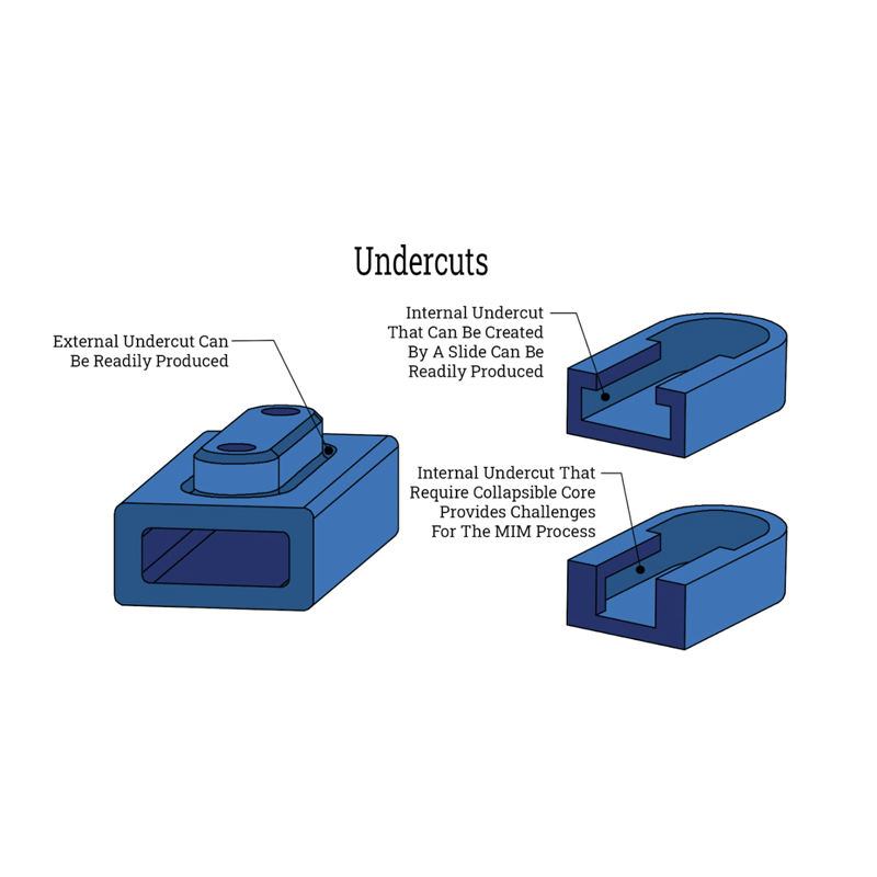
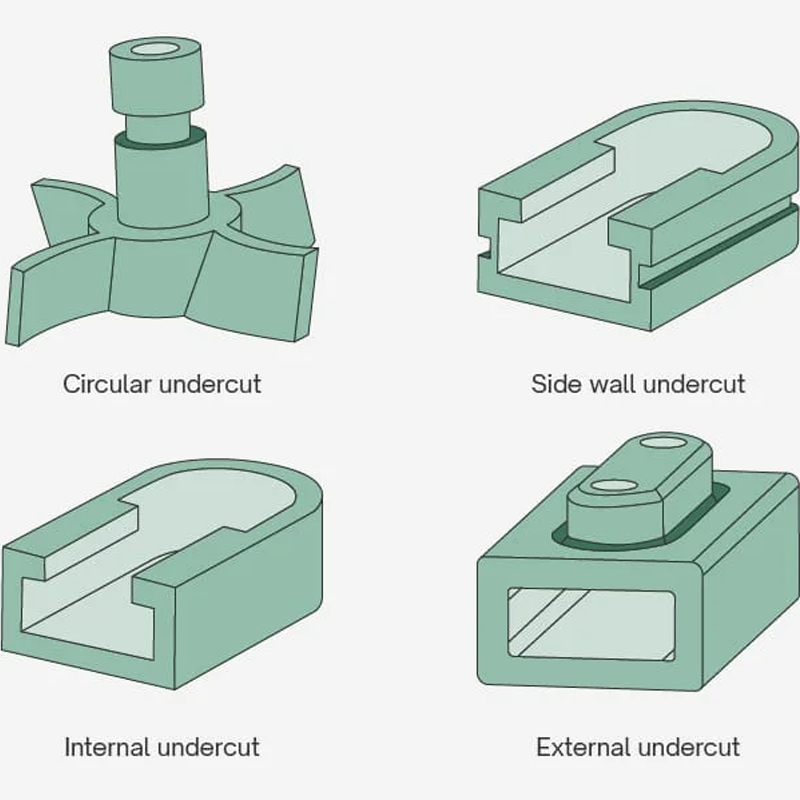
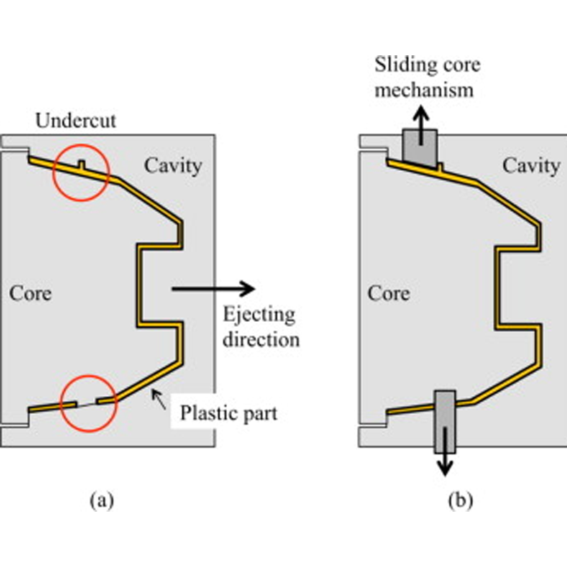
An undercut is any feature that prevents a part from being ejected straight out of a two-half mold. Side holes, hooks, internal ribs, locking tabs, and certain thread profiles are common examples. While these geometries add essential functionality — snap fits, sealing surfaces, mechanical retention — they also force toolmakers and mold designers to introduce moving elements, flexible designs, or secondary operations. The goal of good DFM (design for manufacturability) is to achieve the required function with the least complex, most repeatable molding solution possible.
1 — Shift the parting line where possible
The simplest, lowest-cost way to handle many undercuts is to reorient the part so the feature becomes part of the parting line. Changing the parting line or rotating the part in the cavity often lets the two mold halves form and release the feature without any additional mechanisms.
Practical tips from Toolingsun:
- Review cosmetic and functional faces before moving the parting line — you don’t want visible seams on a primary surface.
- When you shift the parting line, double-check draft directions and gate location to preserve flow and minimize knit lines.
- Advantages: no extra moving hardware, lower tool cost, easier maintenance, faster cycles.
- Tradeoffs: may require compromises in part appearance or assembly orientation.
2 — Use side-actions (cam slides) for robust, repeatable undercuts
When geometry cannot be solved by parting line changes, mechanical side-actions (cam-driven slides) are a standard industrial answer. Slides move perpendicular to the mold’s open direction to form and then retract from undercuts before ejection.
Key engineering notes:
- Side-actions are durable and precise — excellent for high-volume production where repeatability matters.
- Typical travel ranges we design for at Toolingsun are up to ~2.9 in (73.7 mm) with usable slide heights and widths sized to the cavity layout. (Exact slide specs depend on mold base and machine selection.)
- Materials like nylon (PA), POM and PC pull cleanly from slides. Flexible materials (TPE, LDPE) may adhere or tear and often need bumpoffs or slide coatings.
- Considerations: side-actions increase tool complexity, maintenance and upfront cost but often reduce part cost in large runs by enabling automation and eliminating manual insert handling.
3 — Bumpoffs / stripping features for flexible materials
Bumpoffs (stripping release) rely on material elasticity rather than mold movement. The part flexes over a radiused feature during ejection and “bumps off” the core. This is ideal for snap-fits, thin ribs, and many TPE/TPU/LDPE designs.
Design guidance:
- Keep transitions smooth and avoid sharp corners; use large radii and tapered walls to help the part stretch without tearing.
- Limit undercut depth and wall thickness so the material can flex reliably over many cycles.
- Use uniform ejection pressure (ejector plates or pneumatic rings) to prevent local overstress.
- Liquid Silicone Rubber (LSR) often allows more aggressive undercuts because of its high elongation—if application allows, LSR can be a game changer for integrated seals and soft touch features.
4 — Hand-loaded inserts for prototypes and low volumes
For prototypes, R&D runs, or small volume production where the cost of slides is hard to justify, hand-loaded inserts are a practical option. Metal inserts are manually placed into the cavity prior to injection and removed after the shot.
When to choose inserts:
- Low to medium volume—cost of automation outweighs benefits.
- Complex localized features that would require costly slide geometry.
- Rapid design iterations where you need to change insert geometry without remaking the entire tool.
Limitations include longer cycle times and operator handling. Toolingsun’s one-stop service includes short-run tooling and manual insert workflows for customers validating designs before committing to production molds.
5 — Telescoping / sliding shutoffs for built-in undercut formation
Telescoping or sliding shutoffs are elegant in many designs: one cavity half contains a machined projection that slides into a receiving pocket in the opposite half, shutting off polymer flow and forming interlocking features without separate moving cams.
Advantages:
- Lower maintenance than cam slides because the action is self-guiding and compact.
- Good for snap fits, hooks, and interlocks where both mating surfaces are machined in their respective halves.
Design notes: - Provide generous draft (3°+ per side) to avoid metal-on-metal rubbing and flashing.
- Ensure robust alignment features to prevent wear and preserve long tool life.
- Telescoping shutoffs are particularly attractive when tool space is limited and when high-speed cycling is needed.
6 — Optimize part design and use secondary operations when appropriate
Sometimes the most cost-effective solution is to reengineer the part slightly or to perform a post-mold secondary operation. Design choices that dramatically simplify molding include adding draft, reducing undercut depth, and core-ing thick sections.
DFM best practices:
- Minimum draft: 1–3° depending on surface finish and resin.
- Uniform wall thickness: minimizes sink and warp, helps consistent ejection.
- Use radii and ribs to strengthen thin walls instead of adding complex undercut geometry.
- For complex small runs, consider molding a simpler shape and machining or drilling the complex features afterward — this often beats expensive mold actions for low volumes.
Materials and process considerations
Undercut strategy is material dependent. Here are practical pairings we use at Toolingsun:
- Rigid engineering plastics (PA, PC, ABS): Side-actions or telescoping shutoffs work well.
- Flexible TPE/TPU/LSR: Bumpoffs and material elasticity solve many undercuts cleanly.
- LSR: Allows aggressive undercuts and integrated seals due to extreme elongation and recovery.
- For multi-shot or overmolded parts, coordinate runner/gate placement to avoid trapped material and to ensure good bond at interfaces.
Cost, cycle time and lifecycle tradeoffs
Choosing between slides, inserts, or DFM changes comes down to volume and lifecycle:
- Low volumes: hand inserts or post-machining are usually cheapest.
- Mid volumes: consider telescoping shutoffs or simple slides.
- High volumes: robust cam slides and full automation often yield the best total cost of ownership despite higher tool cost.
Toolingsun helps customers run a simple ROI analysis — factoring tooling amortization, cycle time, maintenance, and expected part reliability — so the manufacturing route aligns with business needs.
Validation, testing and production readiness
Before making a production tool, Toolingsun recommends:
- Prototype iterations (3D printed or aluminum molds) to validate parting lines and undercut solutions.
- Full DFM review and mold flow analysis to spot knit lines, air traps and cooling issues.
- Trial runs with material and process settings that match final production (shot size, hold pressure, cooling time).
- Lifecycle testing: mechanical fatigue, insertion/removal cycles for snap fits, and environmental aging for elastomers.
Conclusion
Undercuts don’t have to be design showstoppers. With the right combination of part reorientation, mechanical slides, bumpoffs, telescoping shutoffs, or insert strategies, you can meet functional requirements while controlling tooling cost and production risk. At Toolingsun we combine hands-on mold engineering, one-stop service from DFM through production, and factory experience to recommend the solution that matches your volume, part complexity, and budget.
If you’d like, upload your CAD model today or contact our technical team for a free DFM review. We’ll assess undercuts, recommend the most cost-effective molding strategy, and provide a quote so you can move from concept to high-quality production with confidence.