
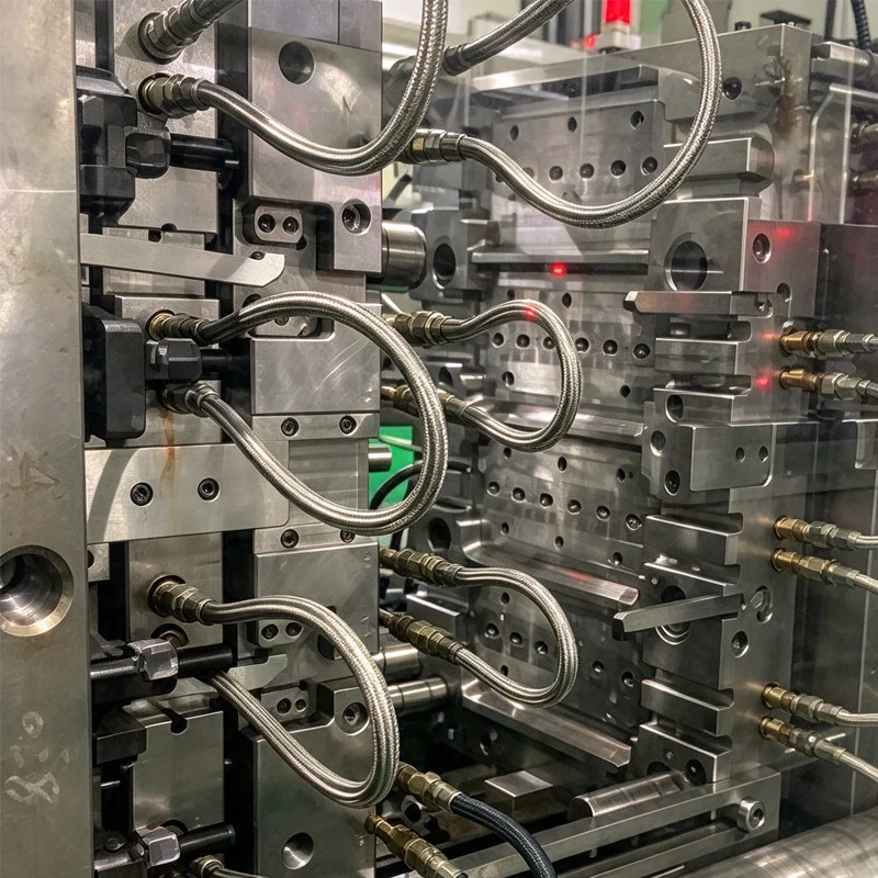
Industry Background: Why Verification Has Become a Sourcing Question
When a tool is built overseas, the buyer rarely stands next to the measuring machine. Measurement data is therefore the evidence on which a tool is corrected, approved or rejected.
Measurement Feeds the Correction Loop
ZEISS describes first article inspection of plastic parts as work often done under time pressure, because the mold making department is waiting for metrology feedback on whether corrections are needed. The ZEISS guidance covers first article inspection run from a CMM measurement plan, a CAD model or a PMI data set that carries GD&T. See the ZEISS-owned GOM overview of first article inspection for plastic parts.
What “Verification” Covers
A mold is verified at several points: steel components, EDM electrodes, T1 samples and later production samples. Toolingsun’s project management page lists dimensional tolerance analysis, pilot production, 3D and 2D inspection and mold acceptance as steps handled by the project team.
Why Buyers Now Ask About Methods, Not Just Equipment Lists
An equipment list does not show whether a feature was measured correctly. Before approving a supplier, ask which instrument checks which feature, to which standard, and what report comes out.
Why It Matters: Measurement Decides Whether a Tool Is Corrected, Approved or Rejected
Inspection Data Drives Tool and Process Correction
GOM explains that measurement results allow fast determination of correction values for tool geometry, such as sink marks, warpage and shrinkage. They also feed process parameters, including holding pressure, temperature control and filling time. A weak measurement method sends the correction in the wrong direction.
Schedule Impact Between T1 and T2
Toolingsun’s production molds page gives a first tool (T1) lead time of 4–8 weeks, followed by roughly 1–2 weeks of adjustments and texturing for T2 samples. Each unclear measurement result adds a loop to that sequence.
Approval Disputes Start With an Unclear Method
If the datum scheme or measurement method differs between buyer and supplier, the same sample can pass at one site and fail at the other. Agreeing the method before T1 removes that argument.
Market Observation: What Published Standards and Metrology Sources Specify
CMMs Are Verified Against the ISO 10360 Series
ISO 10360-2:2009 specifies acceptance tests that confirm a CMM performs as the manufacturer states when measuring linear dimensions. It also specifies reverification tests so the user can check performance periodically. ISO’s page shows the standard was last reviewed and confirmed in 2026, so it remains current. The same page notes that it applies to contacting probing systems and does not explicitly apply to optical probing, which is why optical systems need their own verification.
GD&T Is the Language of the Inspection Report
ASME Y14.5 sets the symbols, rules and definitions for stating dimensions and tolerances on drawings and digital models. ASME lists the current edition as Y14.5-2018 (R2024). If your drawing uses GD&T, the supplier’s inspection program should evaluate the same datums and callouts.
First Article Inspection Can Follow a Plan, a CAD Model or PMI Data
GOM states that first article inspection can be run from a CMM measuring plan, a CAD model or a PMI data set with GD&T. Choose the basis in advance, because it determines what “pass” means.
Full-Surface Optical Measurement Adds Coverage
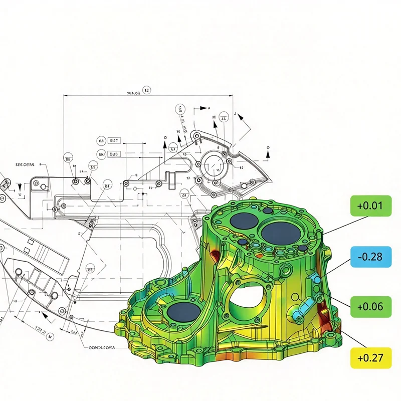
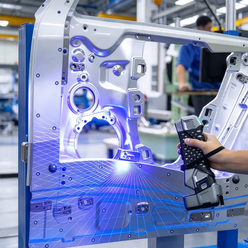
GOM describes its ATOS optical 3D system as a non-contact method that measures complete surfaces of tools, electrodes and molded parts. Its listed applications include sink marks, warpage and shrinkage. Full-field data also supports nominal-to-actual comparison during CNC machining of the tool.
Cavity Comparison and Tool Camber
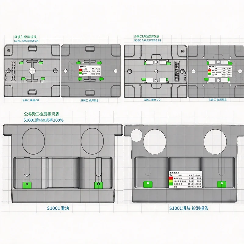
GOM lists cavity comparison and tool camber among the inspection tasks of first article work. For multi-cavity molds, a per-cavity report shows whether one cavity drifts from the others.
The Inspection Toolkit: What Each Instrument Verifies
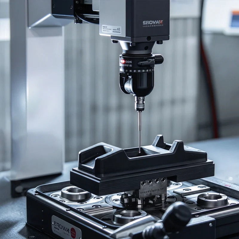
Coordinate Measuring Machines (CMM)
A contact CMM measures dimensions and positions on mold components and on T1 samples against datums. Ask when the machine was last verified, in line with the ISO 10360 acceptance and reverification approach. Toolingsun lists CMM inspection reports among its quality documents on the Why Toolingsun Mold page.
Optical and 2.5D Measuring Systems
Non-contact optical or 2.5D systems suit thin walls, small holes and flat profiles that a probe could deform. Toolingsun lists 2.5D precision detection among its test equipment on the same page.
3D Scanners
Optical 3D scanning compares the full surface with the CAD model and produces a deviation map. It is most useful for warpage, sink marks and free-form surfaces. Buyers should ask which features the scanner measures and which features still go to the CMM.
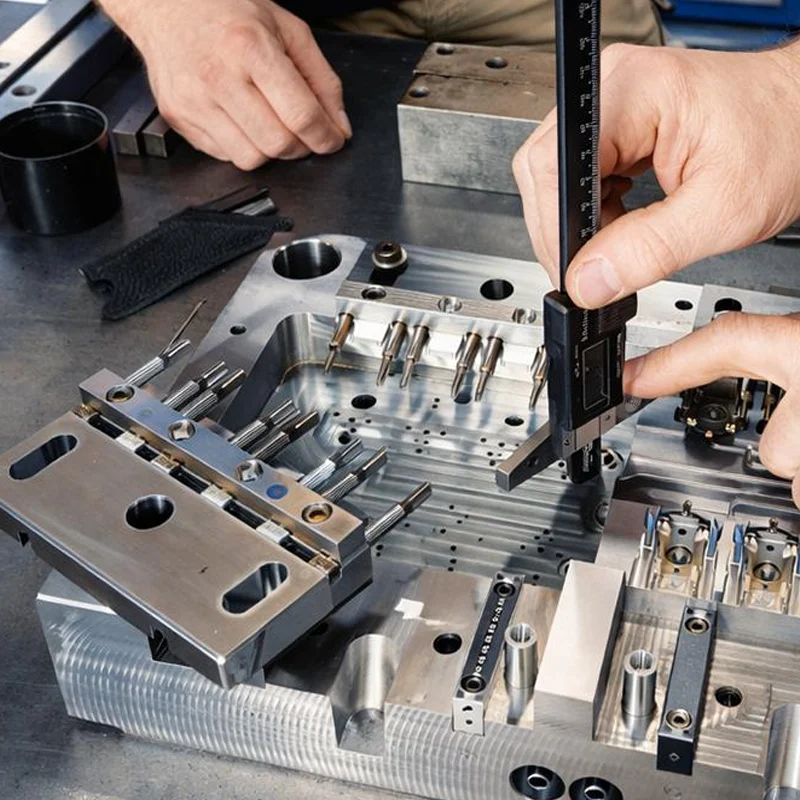
Height Gauges and Handheld Gauges
Calibrated height gauges and handheld gauges cover quick shop-floor checks during machining and sample review. Treat them as screening tools rather than final evidence for tight tolerances.
Surface Roughness and Cosmetic Evaluation
Texture and gloss are usually judged against an agreed finish standard and an approved sample, with roughness testers used where Ra is specified. Agree the finish standard early, using the surface finish options as a common reference.
Hardness Testing of Mold Steel
Hardness testing after heat treatment confirms that steel components reach the specified hardness. Request the hardness record together with the mill certificate, because the two together prove what is inside the tool.
Electrode Verification Before EDM
EDM erodes the cavity with a graphite or copper electrode, so electrode accuracy transfers into the steel. Toolingsun lists on-line electrode detection among its test equipment, alongside 4 Makino sinker EDM machines and 5 Sodick wire EDM machines.
Material and Environmental Testers
Toolingsun also lists a tensile strength tester and a constant temperature and humidity tester. These support material and conditioning checks for molded parts. They complement dimensional tools and do not replace them.
Toolingsun Perspective
Johnny is a Senior Tooling Engineer at Toolingsun with more than 20 years of experience in injection mold design, tooling manufacturing, mold inspection, and production validation. He specializes in mold quality verification, first article inspection (FAI), dimensional measurement, CMM inspection, mold trials, and engineering improvement for export tooling projects. Throughout his career, Johnny has worked with global brands, OEM customers, and sourcing teams to improve tooling reliability through structured inspection methods and data-based decision making. His focus is helping customers understand measurement evidence, inspection processes, and quality documentation needed for stable mass production.
Practical Decision Framework: Eight Questions to Ask About a Mold Supplier’s Inspection Capability
Use this list on your next supplier call.
1. Which Instrument Verifies Which Feature?
Ask for an inspection plan that maps features to methods. A simple map looks like this:
| Feature | Typical method | Evidence to request |
|---|---|---|
| Critical cavity and core dimensions | Contact CMM | CMM report with datum scheme |
| Thin walls, small holes, flat profiles | Optical or 2.5D system | Method and report |
| Free-form surfaces, warpage, sink marks | 3D scanning | Nominal-to-actual deviation map |
| Texture and cosmetic zones | Visual check against approved sample | Texture standard and sample |
| Steel hardness | Hardness test after heat treatment | Hardness record and mill certificate |
| EDM electrodes | Electrode inspection before burning | Electrode inspection record |
| Function (leak, impact, pressure) | Test per customer specification | Test report |
2. How Is the CMM Verified and Maintained?
Ask for the latest verification certificate and how often reverification is done. The ISO 10360 series exists so a user can periodically reverify performance.
3. Is the Measuring Environment Controlled?
Ask whether measurement is done in a temperature-controlled room, and how parts are stabilized before measurement. Plastic samples and steel components both change dimension with temperature.
4. What Datum Scheme and GD&T Does the Report Use?
Provide your datum scheme with the 2D drawing. If the report uses different datums from the drawing, the numbers cannot be compared.
5. What Reports Come With T1 Samples?
Typical documents are an FAI report, CMM data, material certificates and, for automotive programs, a PPAP package. Toolingsun states it supplies FAI, PPAP, material TDS, CMM inspection and SPC reports.
6. How Are Multi-Cavity Differences Reported?
Request cavity-by-cavity data, not an average. A cavity comparison shows whether one impression drifts from the others.
7. How Do Findings Return to the Tool?
Ask how deviations become tool corrections and how they are recorded as engineering changes. Toolingsun’s project management page lists mold corrections and engineering changes among the project team’s duties.
8. Who Reviews the Data?
Agree who approves the measurement program and who signs off the first article. Ask for raw measurement data and the inspection program, not only a summary page.
How Toolingsun Verifies Molds and Samples
If you are sourcing a production tool, Toolingsun’s production molds and export injection molds and tooling services follow the loop described above. The points below come from the company’s published pages. Tolerance and life figures are company statements, so confirm them against your drawing and measurement method in the RFQ.
Equipment on the Shop Floor
On its about page and Why Toolingsun Mold page, the company lists a Hexagon 3D tester for precision workpiece detection, 2.5D precision detection, on-line electrode detection, a tensile strength tester and a constant temperature and humidity tester. For toolmaking it lists 2 high-speed CNC machines plus 7 other CNC machines, 4 Makino sinker EDM, 5 Sodick wire EDM and 5 high-precision grinders.
Documentation Package
Toolingsun states it provides First Article Inspection, PPAP, Material Technical Data Sheets, CMM inspection and SPC reports. Its production molds page also lists formalized inspections, FAIR, IQ/OQ/PQ and material traceability.
Sampling, Correction and Approval
Under the company’s injection molding and mold service, DFM analysis is approved by the customer before tool construction begins. A golden sample is then sent for approval before production. T1 lead time is stated as 4–8 weeks, with 1–2 weeks of adjustments to reach T2 samples. For export tools, a 3D tool design is sent for your approval before the build.
Stated Tolerance Targets
Toolingsun states that mold size tolerance can reach 0.005 mm and product size tolerance 0.03 mm. The company also states a service life of up to 1 million cycles. Ask which instrument and method verify these figures on your part.
Fit for Regulated Programs
The company holds ISO 9001:2015 and IATF 16949 certifications and operates an ISO-certified Class 8 clean room for medical components. For program-specific examples, see its medical mold and automotive mold pages.
What This Means for Your Brand
From Inspection Data to Supplier Confidence
Verification data is the first hard evidence of a supplier’s discipline. A supplier who can show method, instrument and report for each feature usually shows the same discipline in DFM, trials and maintenance.
The Commercial Implication
Inspection records are an asset. They shorten PPAP, support tool transfers and give you a baseline when a mold returns for repair. Write the agreed measurement method and report format into your tooling agreement, and your later quality discussions start from shared numbers.
Conclusion
Mold quality verification relies on a combination of contact CMMs, optical systems, 3D scanning and supporting instruments, each matched to specific features. Ask for the inspection plan, the verification status of the machines, the datum scheme and the report format before T1, and use the eight questions above to compare suppliers on evidence.
FAQ
1. Is a CMM report enough to approve T1 samples?
No. A CMM report covers dimensions. Cosmetic zones, texture and function also need review. Toolingsun’s Why Toolingsun Mold page lists leak, impact and pressure testing by customer specification as functional tests. Add them to the approval criteria where they matter.
2. How often should a CMM be reverified?
ISO 10360-2 provides reverification tests so users can check performance periodically but leaves the interval to the user’s quality system. Ask for the date of the last verification and the interval the supplier follows.
3. Can a 3D scanner replace a CMM?
They complement each other. GOM positions optical 3D systems for full-surface comparison, while ISO 10360-2 addresses contact CMMs and does not explicitly cover optical probing. Ask which features each method measures and how each is verified.
4. What happens when a sample is out of tolerance?
The data shows whether the cause lies in tool geometry or in process settings. GOM notes that results feed corrections to both tool geometry and parameters such as holding pressure, temperature control and filling time. Toolingsun lists mold corrections and engineering changes among its project team’s duties.
5. Does inspection equipment verify the mold steel?
Not on its own. Dimensional instruments check geometry. Steel grade and hardness are confirmed through mill certificates and hardness records after heat treatment, so request both with the tool documentation.
About the Author
Johnny is a Senior Tooling Engineer at Toolingsun with more than 20 years of experience in injection mold design, tooling manufacturing, mold inspection, and production validation. He specializes in mold quality verification, first article inspection (FAI), dimensional measurement, CMM inspection, mold trials, and engineering improvement for export tooling projects. Throughout his career, Johnny has worked with global brands, OEM customers, and sourcing teams to improve tooling reliability through structured inspection methods and data-based decision making. His focus is helping customers understand measurement evidence, inspection processes, and quality documentation needed for stable mass production.
References
- International Organization for Standardization (ISO), ISO 10360-2:2009 — Acceptance and reverification tests for coordinate measuring machines (CMM), reviewed and confirmed 2026
https://www.iso.org/standard/40954.html - American Society of Mechanical Engineers (ASME), Y14.5 Dimensioning and Tolerancing, 2018 edition (R2024)
https://www.asme.org/codes-standards/find-codes-standards/y14-5-dimensioning-tolerancing/2018 - GOM (ZEISS), Plastic Parts and First Article Inspection
https://www.gom.com/en/solutions/plastics/plastic-parts-and-first-article-inspection
Need Engineering Feedback on Your Inspection Plan?
- Upload Your 3D Files and 2D Drawings With Critical Dimensions
- Request DFM and Mold Flow Review
- Discuss Measurement Method and Report Format Before T1
- Start Your Tooling Project
Share your files and your acceptance criteria, and the Toolingsun team will review the inspection approach before tooling starts. Contact the Toolingsun engineering team.