
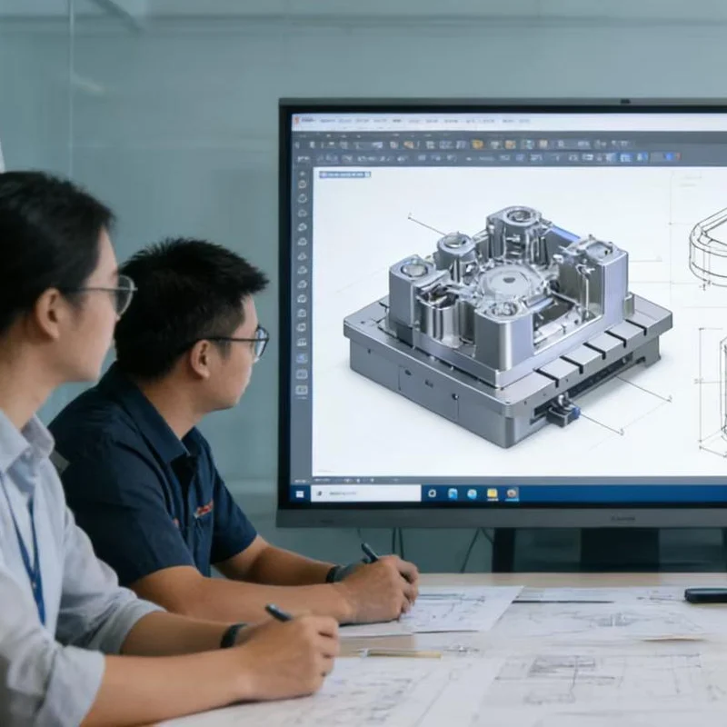
Industry Background: The Shift Toward Early Supplier Involvement
The transition from conceptual product design to physical mold manufacturing represents the highest financial threshold in OEM product development. Historically, many brands treated design and manufacturing as isolated phases. Today, that linear approach is shifting rapidly.
The Cost of Traditional Linear Manufacturing
In a traditional “design-then-build” model, industrial designers finalize a CAD model and pass it directly to procurement, who then sources a tooling supplier. By the time mold engineers review the files, the brand has already locked in functional aesthetics. Modifying the design at this late stage creates friction between design intent and manufacturing reality, often resulting in delayed product launches and compromised structural integrity.
Adoption of Concurrent Engineering
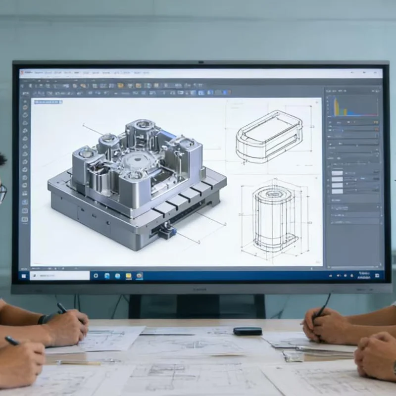
To mitigate tooling risks, B2B purchasing managers and brand engineers are increasingly adopting concurrent engineering models. In this framework, tooling suppliers are brought into the design phase long before the first block of P20 or H13 steel is cut. This Early Supplier Involvement (ESI) ensures that the geometry is optimized for the physical realities of melted resin, cooling channels, and ejection systems.
Regulatory Pressure on Material Usage
Stringent environmental regulations are forcing brands to rethink material selection. Moving from virgin plastics to recycled composites or bio-based resins fundamentally alters the material’s shrink rate and flow behavior. Modifying the product design early to accommodate these new material properties is no longer optional; it is a compliance necessity.
Why Modifying Design Before Mold Making Matters
Locking in a flawed design before cutting steel guarantees compounded problems during mass production. Addressing manufacturing constraints during the CAD phase is the most effective way to protect project ROI.
Tooling Cost Optimization
Once a mold is machined, “steel safe” modifications—where metal is removed to add plastic—are possible but expensive. However, adding steel back into a mold to reduce wall thickness or fix a structural weak point often requires welding or entirely rebuilding the core or cavity. Pre-tooling modifications eliminate these unnecessary capital expenditures.
Eliminating Cycle Time Inefficiencies
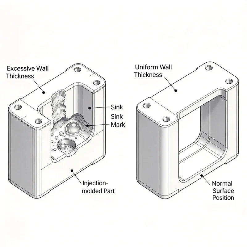
Cycle time dictates the final unit cost of any plastic component. If a design features overly thick sections, the cooling time required before ejection increases exponentially. By modifying the design to core out thick areas and introduce structural ribbing, engineers can shave seconds off the cycle time, yielding massive cost reductions over high-volume production runs.
Preventing Structural Failures in Mass Production
Injection molding relies on uniform pressure and temperature. Designs that force plastic to flow from thin sections into thick sections often result in structural voids, sink marks, or extreme internal stress. Modifying the part geometry beforehand ensures a uniform flow front, significantly reducing the risk of component failure in the field.
Market Observation: The True Cost of Late-Stage Design Changes
Industry data highlights why proactive design adjustment is the most critical phase of product development.
Data from Recent Manufacturing Studies
According to Grand View Research, the global plastic injection molding market size is expanding rapidly, demanding faster time-to-market from OEM brands [cite: 1.1.2]. However, pushing a flawed design into the tooling phase directly contradicts this goal. Industry consensus shows that modifying a design during the digital DFM (Design for Manufacturability) phase costs a fraction of what it costs to rework a physical steel mold.
Tool Steel Modification Constraints
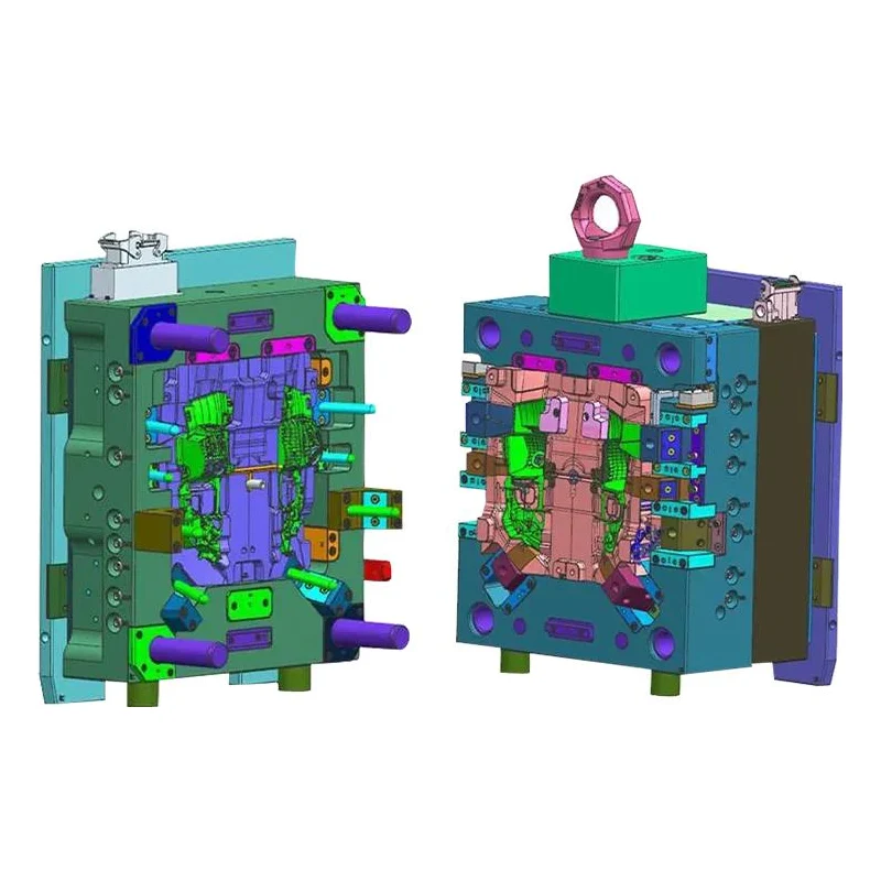
Certain modifications are physically constrained by the chosen tool steel. Hardened steels used in custom plastic injection die cast molds can be extremely difficult to rework after heat treatment. Identifying the need for inserts or lifters before the tooling blueprint is finalized prevents the need for destructive mold modifications.
The Impact of Recycled Materials on Mold Flow
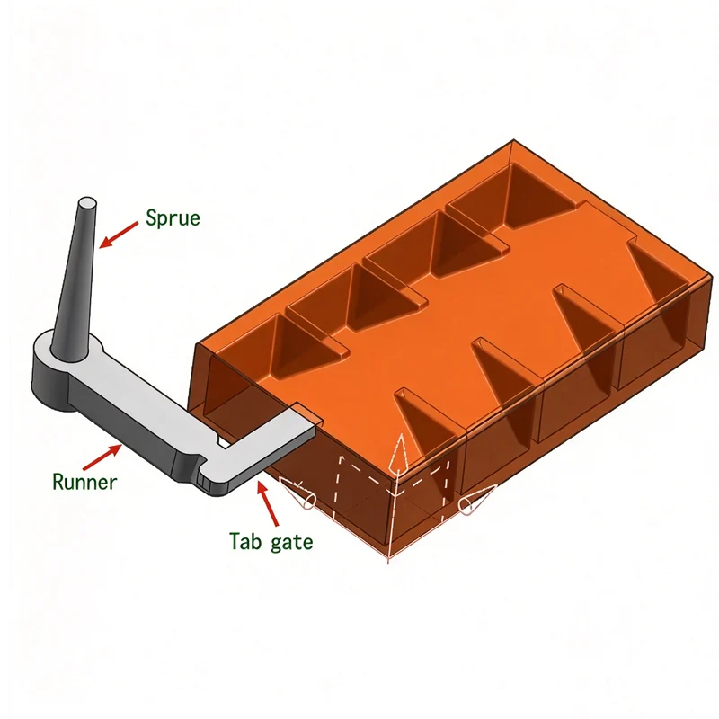
As the U.S. Environmental Protection Agency (EPA) continues to push for sustainable manufacturing practices, brands are integrating higher percentages of PCR (Post-Consumer Recycled) plastics. These materials exhibit distinct flow characteristics compared to virgin resins. A design that works flawlessly for standard ABS may require significant gate and runner modifications when transitioning to a recycled PC/ABS blend.

Engineering Observation: Identifying Structural Flaws Before Tooling
Over the past three quarters, our engineering team has observed a distinct shift in how OEM buyers approach complex geometries. Instead of submitting finalized CAD files for immediate tooling, purchasing managers for automotive and industrial brands are increasingly requesting comprehensive DFM analyses up to four weeks earlier in the project cycle.
Resolving Wall Thickness Variations
During a recent project for an industrial housing unit, our initial analysis identified a wall thickness variation of over 60%. Left unmodified, this would have guaranteed severe sink marks on the cosmetic surface. By working with the client to core out the thick sections and add supportive ribbing in the CAD phase, the aesthetic integrity was maintained while ensuring a stable molding process.
Optimizing Draft Angles for Core and Cavity
Many product designers default to 0-degree draft angles for a sleek, modern look. However, perpendicular walls create immense friction during the ejection phase, leading to drag marks and part distortion. We consistently recommend modifying vertical walls to include a minimum of 1.5 to 2 degrees of draft, depending on the chosen surface texture.
Managing Undercuts with Lifters and Sliders
Undercuts (features that prevent the part from ejecting straight out of the mold) require complex mechanical actions like sliders and lifters. These mechanisms increase tooling investment and maintenance requirements. Whenever possible, we advise modifying the design to eliminate non-essential undercuts, or redesigning snap-fits to utilize pass-through cores, simplifying the mold structure.
Gate Placement for Optimal Resin Flow
The location where molten plastic enters the mold cavity dictates the final cosmetic appearance and structural strength of the part. If a designer places a critical cosmetic surface directly in the path of a required gate, the design must be modified. Shifting the gate to a non-visible edge or utilizing a sub-gate minimizes post-processing labor and cosmetic defects.
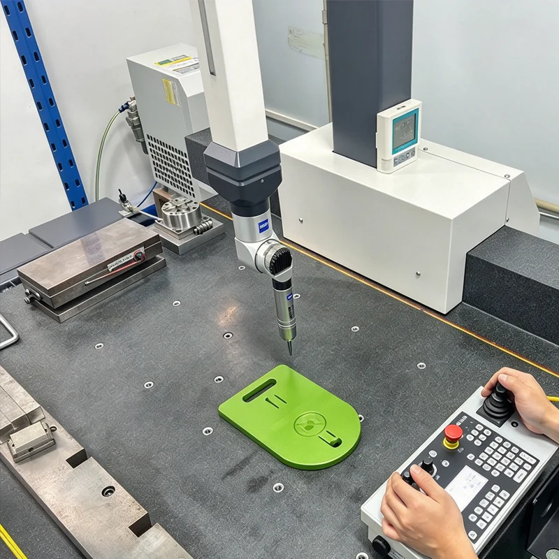
Practical Decision Framework: The DFM Checklist for Buyers
Before authorizing any tooling supplier to purchase steel, product managers should conduct a rigorous review against this framework:
CAD File Feasibility Verification
-
✓ Have all non-essential undercuts been redesigned or eliminated?
-
✓ Is the wall thickness uniform throughout the primary geometry?
-
✓ Have adequate draft angles been applied to all vertical faces based on the required texture?
Shrinkage Rate and Tolerance Alignment
-
✓ Has the specific polymer grade been finalized so the exact shrink rate can be applied to the tooling blueprint?
-
✓ Are the requested dimensional tolerances realistic for the chosen material and injection molding process?
Insert Molding and Overmolding Feasibility Check
-
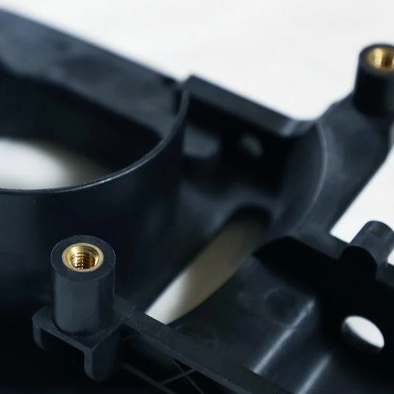
✓ If the design requires insert injection molding, are the metal inserts robust enough to withstand injection pressures without deforming?
-
✓ Is there sufficient plastic wall thickness surrounding the metal insert to prevent cracking during thermal cycling?
Tooling Sun’s Approach to Engineering-Driven Tooling Solutions
For B2B buyers evaluating mold manufacturing partners, the ability to execute design modifications seamlessly is a critical sourcing metric. At Tooling Sun, we bridge the gap between design intent and physical manufacturing through an engineering-first methodology.
Precision Tooling for Complex Automotive and Industrial Parts
Producing components for crucial applications demands structural stability. As an experienced automotive mold maker, our robust Computer Numerical Control (CNC) machine department specializes in optimizing complex geometries before tooling begins. This ensures that intricate features, such as tight-tolerance snap fits or critical sealing surfaces, are manufactured right the first time.
Efficient Mold Frame Sharing Technology
To support cost-effective OEM production, Tooling Sun utilizes mold frame sharing technology alongside rapid prototyping capabilities. By thoroughly analyzing and modifying the part design prior to cutting the core and cavity inserts, we ensure compatibility with shared mold bases. This approach reduces overall tooling investment and dramatically accelerates turnaround times for pilot production.
Reliable Insert Molding Integration
When integrating metal threads or electronic components, the ‘one-shot’ process must be flawless. Our engineering team reviews all CAD models to ensure that metal mold inserts are properly supported within the tool, guaranteeing functional threads and reducing wear over the part’s lifespan.
-
Image Name: Tooling-Sun-Automotive-Insert-Molding-Component.jpg
-
Alt Text: Automotive component manufactured using insert injection molding demonstrating precision tolerance
What This Means for Your Brand
Integrating design modifications before mold manufacturing goes beyond avoiding production defects; it fundamentally impacts how an OEM brand scales its operations.
Reducing Total Cost of Ownership (TCO)
Every design flaw that makes it into the tooling phase multiplies the total cost of ownership. By investing time in early CAD modifications and DFM reviews, brands lock in lower cycle times, minimize material waste, and extend the lifespan of the mold itself.
Aligning Product Design with Supply Chain Realities
A design that is difficult to mold is ultimately difficult to scale. By ensuring that the product geometry aligns with standard injection molding parameters, brands reduce their vulnerability to supply chain disruptions. Parts that mold easily with standard cooling cycles can be produced reliably, maintaining inventory flow and supporting aggressive market expansion strategies.
Conclusion
The distinction between a successful product launch and a delayed, over-budget project often comes down to timing. Engineers must modify product designs before mold manufacturing begins to optimize material flow, ensure structural integrity, and protect the tooling investment. Engaging with a manufacturing partner early in the design phase is the most effective strategy for bringing robust, compliant, and cost-effective products to the B2B market.
FAQ
1. What is the ideal time to conduct a DFM review?
The optimal time for a Design for Manufacturability (DFM) review is immediately after the initial 3D CAD geometry is established, but before any aesthetic surfaces or functional dimensions are strictly locked in by the brand’s marketing or product teams.
2. How do draft angles affect the tooling process?
Draft angles allow the molded part to release smoothly from the steel core and cavity. Without sufficient draft, the vacuum and friction created during ejection can warp the plastic, scuff the surface finish, or cause ejector pins to punch through the part.
3. Can a mold be modified after the steel is cut?
Yes, but it is limited and costly. “Steel safe” changes (removing metal from the mold to add plastic to the part) are relatively straightforward. However, “metal safe” changes (adding metal to the mold to remove plastic from the part) often require expensive welding or remaking entire sections of the tool.
4. What information does a manufacturer need for an accurate DFM analysis?
A precise DFM requires a complete 3D CAD file (STEP, IGES, or X_T format), the specific material grade and manufacturer, the intended surface finish requirements, and the projected annual production volume to determine the appropriate mold steel.
5. How does material selection influence mold design?
Different polymers have drastically different shrink rates and flow characteristics. The mold must be scaled up by the exact shrinkage percentage of the chosen material. Changing materials after the mold is cut will result in parts that are either too large or too small to meet dimensional tolerances.
About the Author
James is a Senior Tooling Engineer at Tooling Sun with extensive engineering background in precision injection molding and custom tooling development. He specializes in Design for Manufacturability (DFM), complex insert molding optimization, and mold flow analysis for automotive and industrial applications. Working closely with global brands and purchasing managers, James focuses on mitigating manufacturing risks through early engineering intervention, ensuring stable, high-volume production architectures for complex plastic components.
References
-
Grand View Researchhttps://www.grandviewresearch.com/industry-analysis/injection-molding-market
-
ASTM International (Standards for Plastics and Tooling)https://www.astm.org/
-
U.S. Environmental Protection Agency (EPA) – Sustainable Manufacturinghttps://www.epa.gov/sustainability/sustainable-manufacturing
Request Engineering Review
- Upload Your CAD Files
- Request DFM Analysis
- Start Your OEM Project
- Request Material Recommendation